I hit a plateau with my B6.2. I have been working on my chassis setup, and I’ve reached a point where I feel comfortable racing around other cars, but I haven’t improved my fastest lap time. The current layout at my local track, Rise Up HobbyTown, has two sections where I’m full lock on the steering and feathering the throttle to make the turn. I feel like I am losing time in those sections by not being flat out on the throttle and hitting the apex via steering input.
The last time I was at the track, there was a low turnout. In all of my practice sessions either I was alone or there was only one other car on the track. Without the noise and commotion of a race going on, I could hear my tires making noise in the turns. While it was cool at first and reminded me of standing close to a go-kart track, there was an awful lot of noise coming from the rear tires, especially in the two corners where I’m “waiting” on the car. I interpreted this noise as the front and rear tires fighting each other and scrubbing speed.
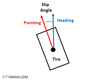
Imagine the car from the top while cornering. Focus on the outside tires – the front is turned and inline (más o menos) with the car’s path while the rear is angled inward towards the center of the car and away from the direction it is going—the difference in where the tire is pointed and the path it actually takes is called slip angle. Regarding the rear end, more toe-in equals more traction because the rear tires are working against the front while cornering. The trade-off is that there is more slip angle, which creates increases rolling resistance and robs speed.
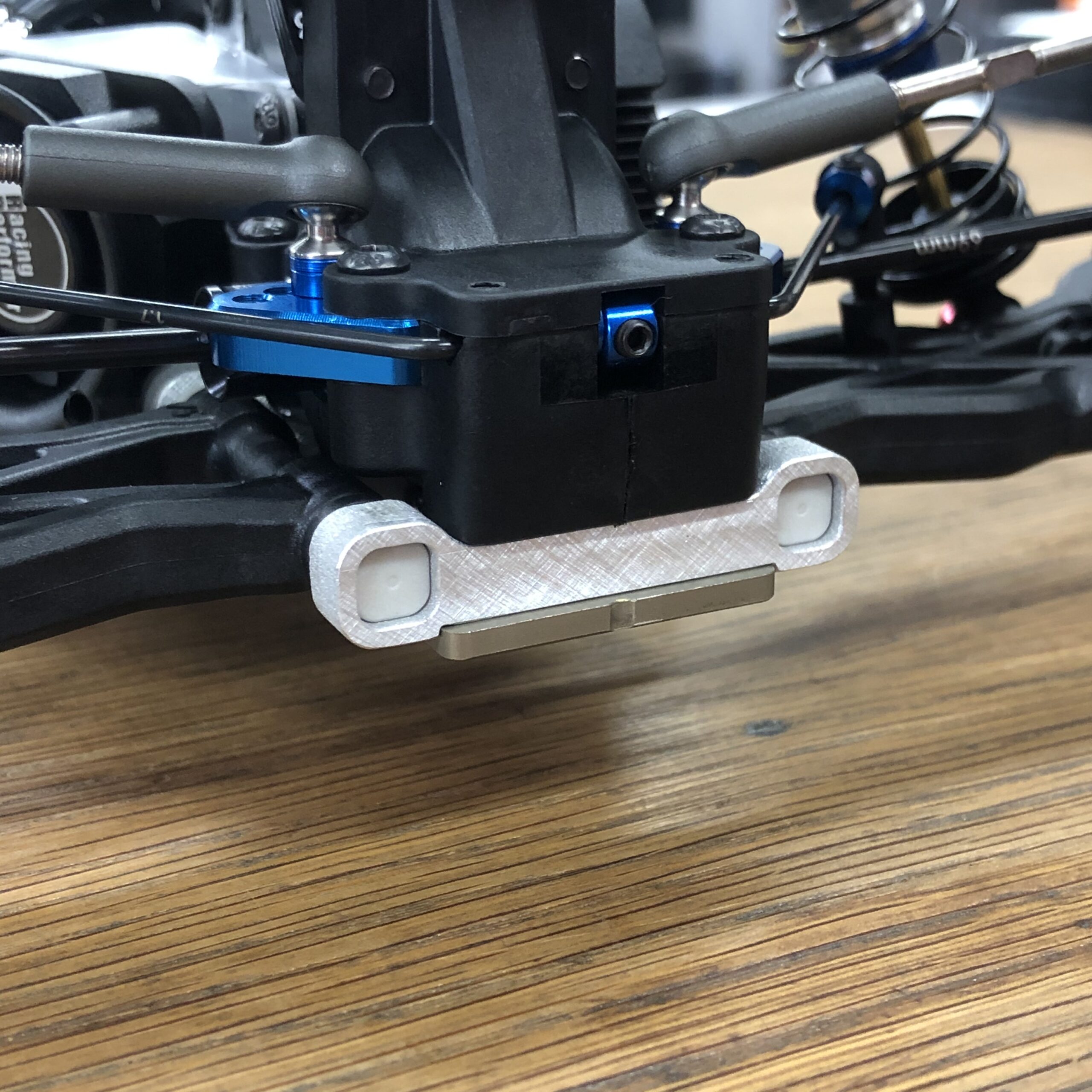
I wanted to try less rear toe-in. This would allow the car to rotate more mid-corner and not square-up as aggressively on exit. The problem is that the kit setup is already at the minimum setting of 1 degree. At the track, I tried to mount an extra “C block” in the rear to have equal width pivots, but the screw holes didnt line up. When I was done fiddling around with these parts, I came up with a plan to make my own.
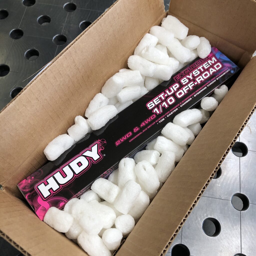
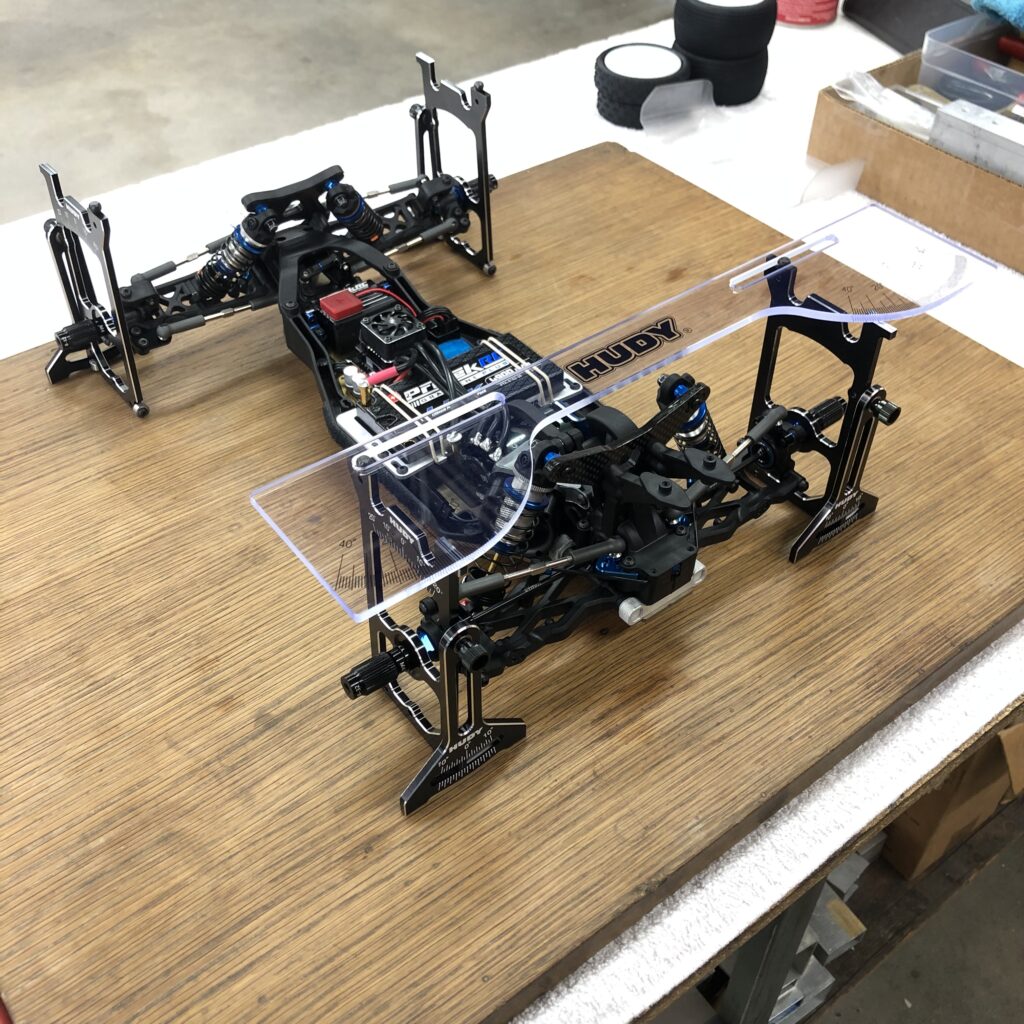
I started by getting one of these setup stations for my buggy. I don’t think these are completely necessary for racing, but I wanted one for this project and some new stuff coming up where this could come in handy.
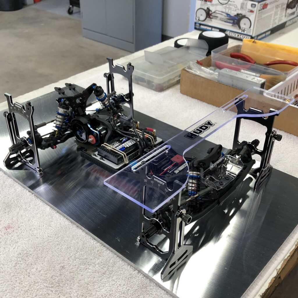
Nice. I assembled the jigs and setup the car on this aluminum plate. The specific grade is Mic-6, and it is extremely flat and smooth. A bit overkill for this but the little bearings at the base of the jigs ride nice on this surface.
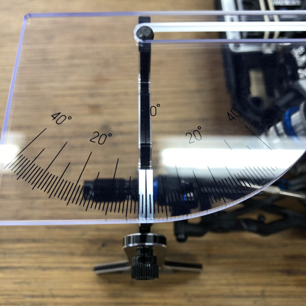
As far as camber and toe measurements, if you build the camber links to the length it says to in the manual, the actual angle in degrees is very close.
Side note: Everyone loves to rave about the Hudy quality, and I have to admit that it is very good, but… One of the thumb nuts that thread onto the axle wasn’t tapped for M4 thread. Not a big deal as I have a tap, but if I didn’t, I’d be bummed that I spent this much money and couldn’t put the kit to use.
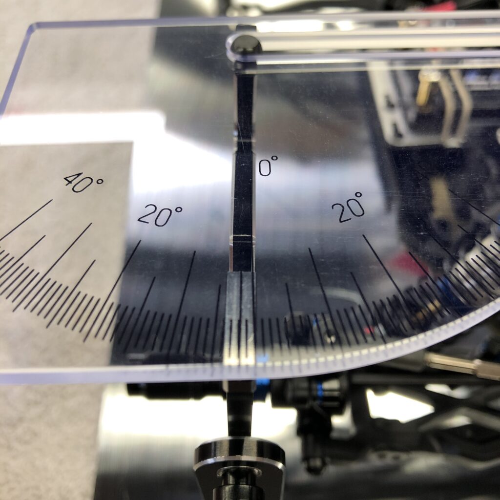
Using the Hudy station, the toe-in on the left rear wheel measures 2 degrees. According to the manual, this is supposed to be 1 degree. The car has a bit of slop but not that much.
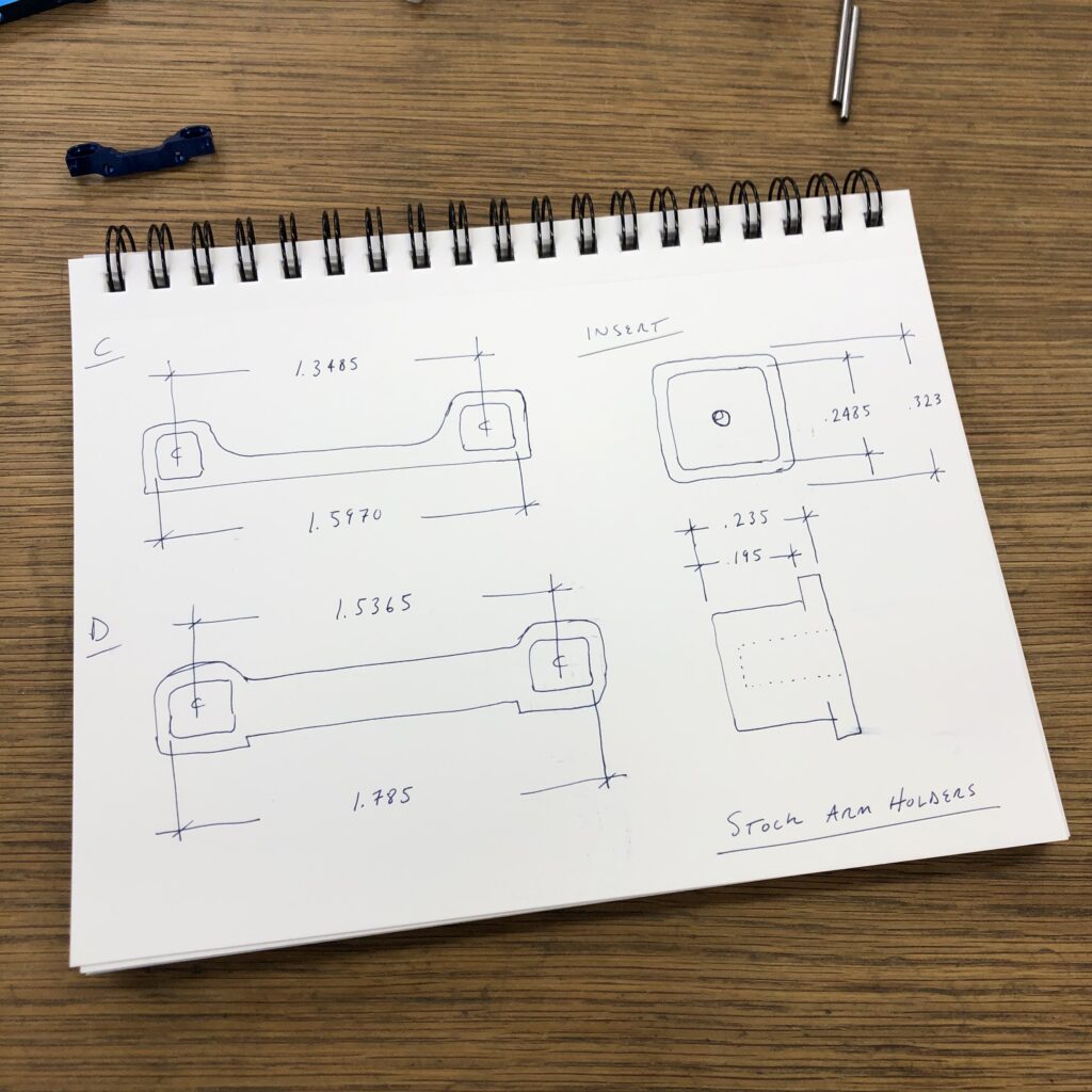
I took measurements of the stock blocks and inserts.
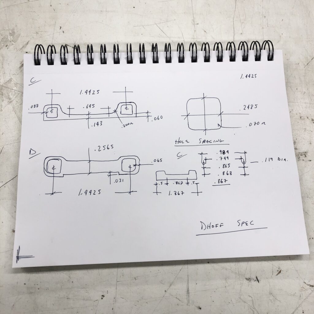
Then I drew these where the front and the rear will have the same dimension center to center. Technically this would allow for rear toe-out, but I’m only interested in zero and up with the ability to have pivot width adjustment at less than stock rear toe-in. I found this width by averaging the stock parts; this should keep the track width close.
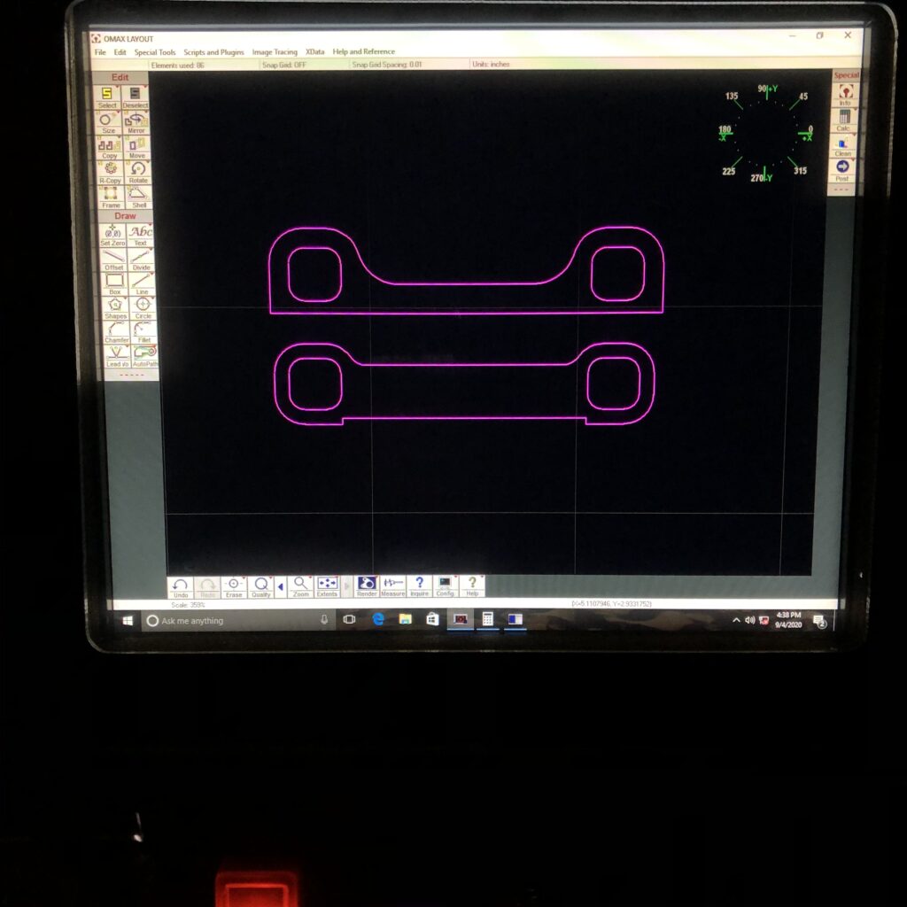
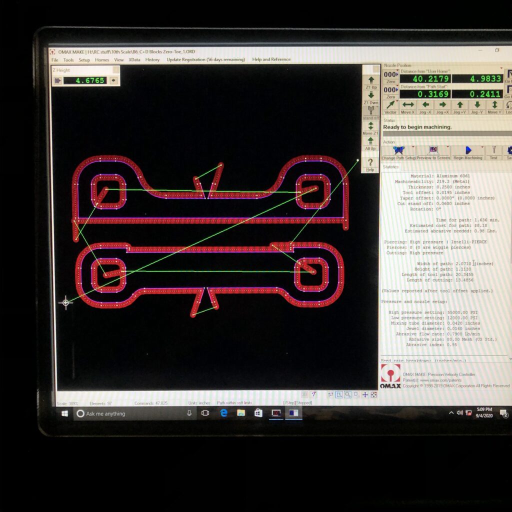
Drawing the parts in the computer and creating a tool path.
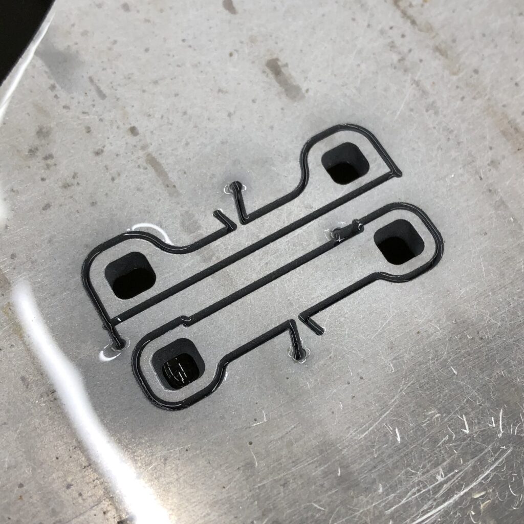
For the first set, I cut them out of a piece of .250″ thick 6061. I bought a little chunk of 7075 to make finals out of later on. After I got these done, I had a few ideas of what I would change – funny how these thoughts always come to mind after the fact.
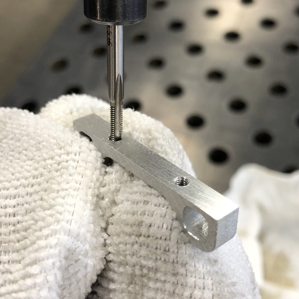
Tapping the holes for the “C block”.
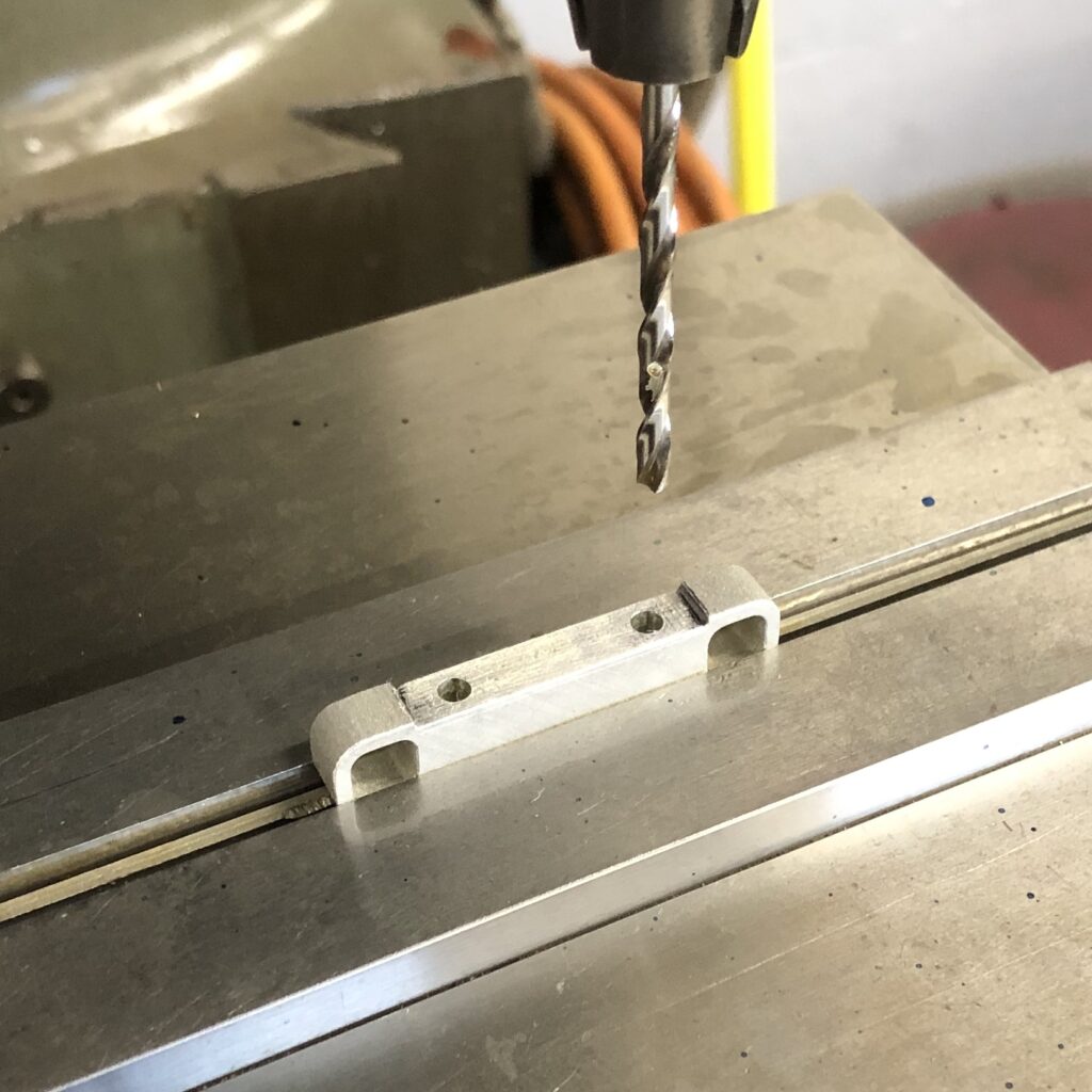
Drilling the 3 mm thru holes in the “D block” – can you tell I come from 1/8 scale?
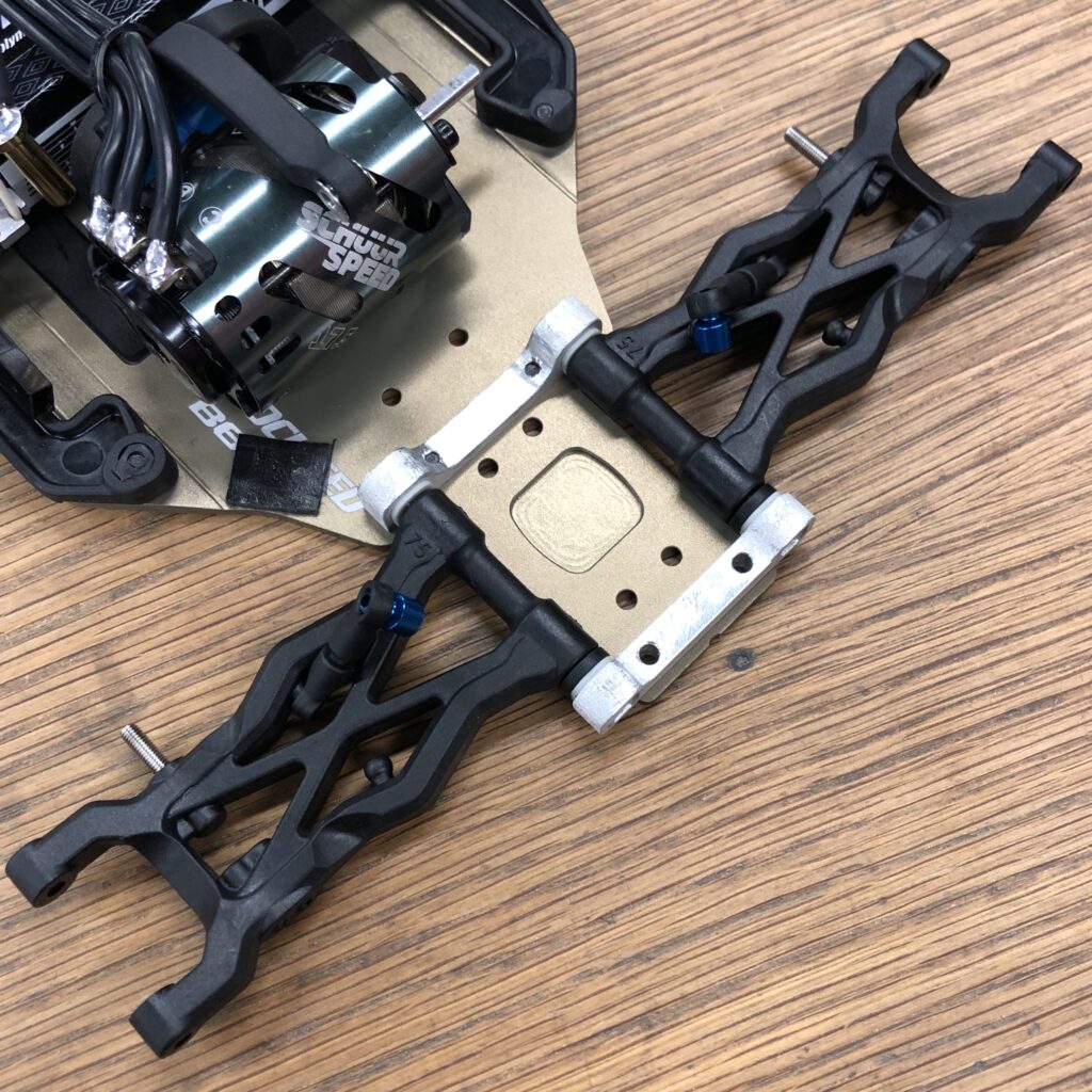
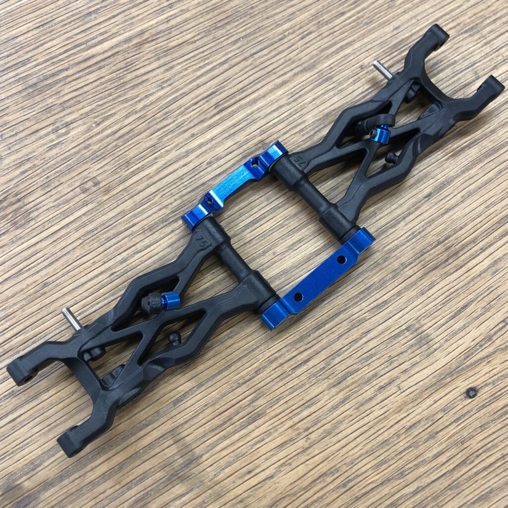
The test fit looks good. I didn’t copy the profile from the top, and I kept the holes in the center. That made it easier to get these done and try them out before I invest too much time. Now the blocks are spaced further apart, so I had to add an extra 1 mm or so spacers behind the arm, no problem.
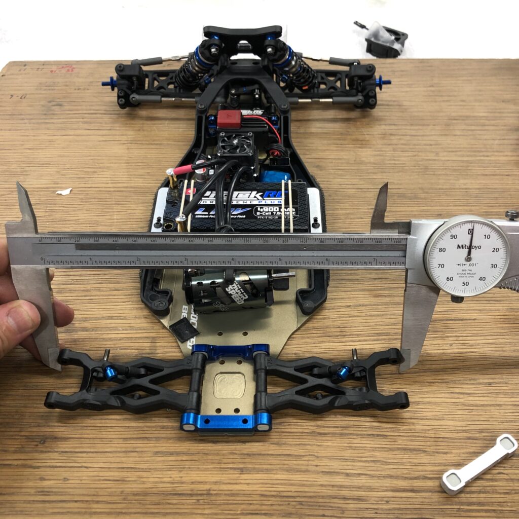
I was curious how the rear track was going to work out. I measured the o.d. of the front and back of the rear arms with the stock arm holders. The average is 7.6325″.
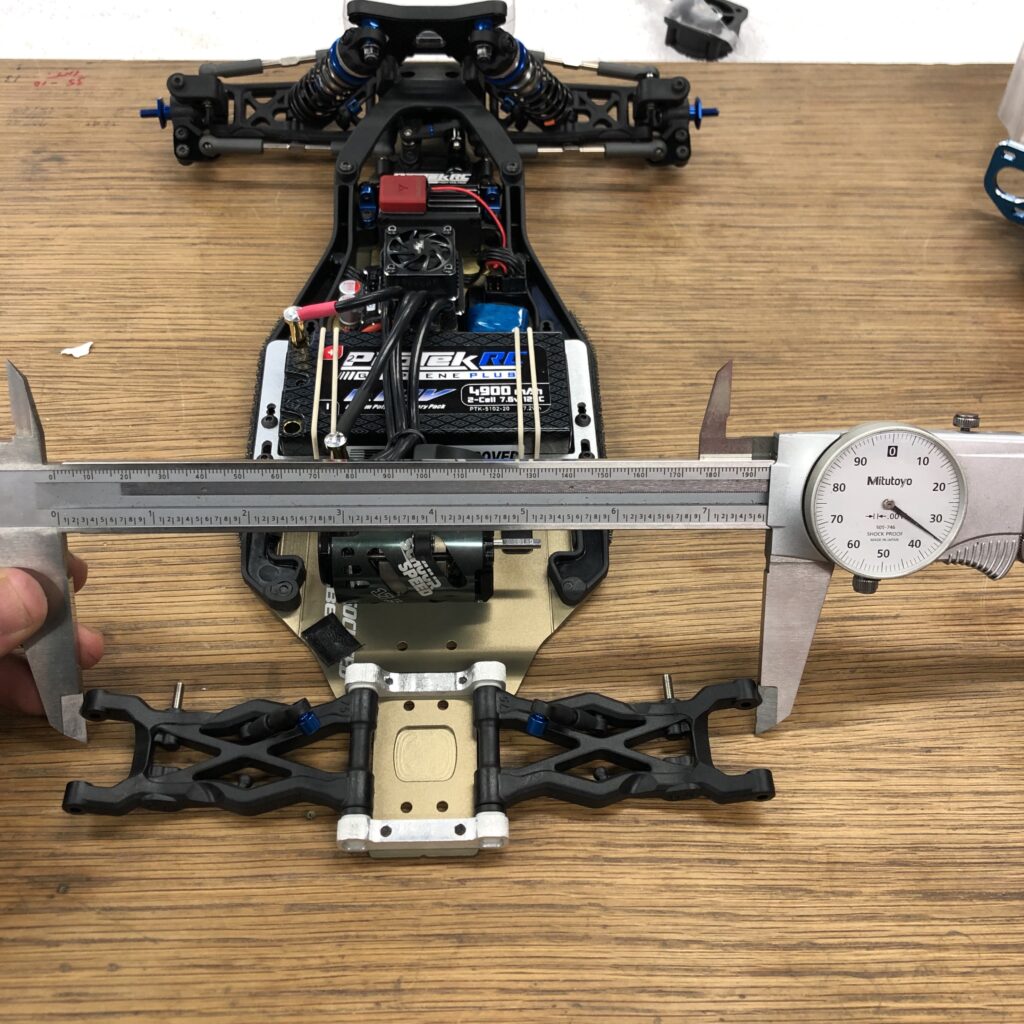
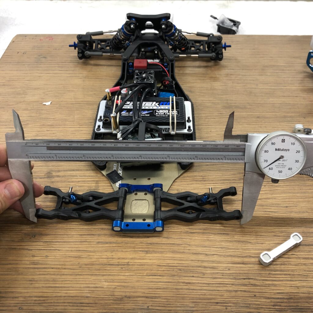
Measuring the o.d. with my rear pivots and “Zero” inserts front and rear – 7.635″ two and a half thousandths off – LOL I’ll take it.
With “Zero” inserts front and rear – Zero degrees rear toe-in, 1-degree anti-squat. I got a set of the new black inserts to have finer adjustments if needed.
I’ve run the car three times with my rear pivots, and the results have been great. More details on lap times and setup changes in the next post, cheers!